 Admin
Admin
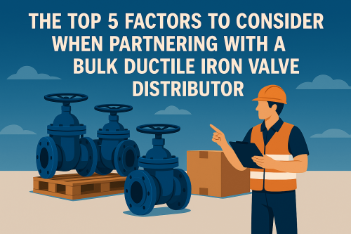
The distributor you use to sell your ductile iron valves can make or break your business operations. As a contractor, engineer, or purchasing manager, regardless of your specific work type, you require a partner whom you can trust to make bulk purchases of valves in a way that keeps your work going and within budget. Ductile iron valves play a vital role in water pumping systems, sewage treatment facilities, and most industrial processes. Working with the right distributor is even more relevant when you require such valves in huge volumes. Here are the five most critical considerations you need to use to make this business decision of paramount importance. 1: Product Quality and Standards The quality of valves that your would-be distributor has to offer is the first thing that you will need to take into consideration. Ductile iron valves are not all of the same quality, and those of poor quality can cause significant issues in the future. What is a Good Valve An ideal ductile iron valve must be according to industry standard, such as AWWA (American Water Works Association) or ISO. Such standards certify that valves can endure real-world pressure, temperature, and conditions. Seek distributors that can offer certificates and documents to demonstrate that their valves meet these expectations. Valves will be of good quality, meaning they will be adequately coated to prevent rusting, run smoothly, and have a uniform wall thickness across the valve body. Testing and Inspection Inquire with your prospective distributor about their testing process. Reliable distributors can pressure test the valves and supply testing reports. Valves should also be checked to identify defects, ensure the correct size, and verify the coating. Indeed, some distributors will provide you with third-party testing services to ensure the quality of the products. This would cost a little more initially; however, it may save you thousands of dollars in replacements, not to mention frustrating project delays. Support and Warranty When a distributor is confident in his products, he will offer meaningful warranties. Select warranties that cover manufacturing and performance. Quality distributors will also provide technical assistance to help you select the appropriate valves for your applications. 2: Availability and Inventory Waiting for valves that should have been provided several weeks earlier is a sure way to mess up a project. When selecting a distributor, it is paramount to consider inventory management and availability. Stock Levels Ask your distributor how much inventory he carries. Distributors with large and well-organized warehouses are typically able to handle fast order processing, particularly for orders of large quantities. Inquire about their best-selling sizes and types to ensure that they are the common ones. Other distributors have sophisticated management software that helps them forecast demand and maintain popular merchandise. This technology would enable the avoidance of stockouts and ensure quicker delivery. Lead Times Gain knowledge of the typical lead times for conventional and special orders. Although bulk orders typically take time to deliver, a competent distributor should provide you with realistic deadlines and meet them. Do not trust distributors who provide unrealistic delivery dates to secure your business. Emergency Orders In other cases, you may be in dire need of valves because of emergency repairs or last-minute projects. Enquire about how potential distributors will be able to accept emergency orders. The superior distributors will have processes in place to prioritize urgent requests and may even maintain emergency stocks in extreme cases. 3: Price and Terms of Payment You should not focus solely on the price in all cases, but it is undoubtedly one of the issues that should not be disregarded, especially when purchasing valves in large quantities. Nevertheless, the most cost-efficient is not necessarily the most affordable. Bulk Pricing Structure Most distributors offer discounts on bulk purchases, although these may vary significantly. Others are based on quantity, and some offer discounts on projects. It is essential to understand exactly how their pricing methods work and what quantity attracts which level of discount. Obtain the prices of various order quantities to determine the best value points. On occasion, it can be worth ordering a little more to generate sizable savings on the per-unit price. Payment Options For large orders, payment terms can be flexible, thereby aiding your cash flow. Seek distributors that may allow net 30, net 60, or even progress payments on huge orders. Some distributors also offer early payment discounts, which can lead to substantial long-term savings. Be cautious of distributors who insist on advance payment unless they offer substantial discounts. It places all the risk on you and may indicate a possible cash flow issue on their part. Total Cost of Ownership Do not only consider the buying price. Include shipping expenses, any additional fees you may incur for returning the item, and the costs of any other services you may require. Even a slightly more expensive distributor that ships free and provides superb support can still be a better deal. 4: Technical Services and expertise Ductile iron valves are available in numerous forms, styles, and sizes. It is enough to have a distributor who is highly technical to save you time, money, and even headaches. Product Knowledge Your distributor should help you select the appropriate valves for your specific applications. They are expected to learn about the various pressure ratings, end connections, and coatings. Good distributors not only take your order but also learn more about your specific application, enabling them to advise you on the best products to use. Identify distributors with engineering-based sales personnel or whose sales personnel have extensive experience in the valve industry. Application Support The top distributors do not simply sell valves; they also provide comprehensive solutions. They offer application support, assist with specifications, and even troubleshoot field problems. This level of support is essential when handling complex projects or unusual applications. Custom Solutions At other times, the standard valves may not be precisely what you need. Search for distributors that can provide custom solutions or modifications tailored to your needs. These could include custom end finishes, end connections, or custom sizes. 5: Reputation and reliability Project success and failure may depend on your distributor's reliability. A distributor's reputation in its industry is often shaped by its reliability and the quality of services it provides to its clients. Track Record Find the background records of potential distributors. What is their experience in business? Have they done anything comparable to what you have in store? Individual distributors who work successfully in supplying valves to extensive infrastructure facilities or industrial sites should also be sought. Verify some of the reviews from other customers, particularly those who share similar needs to yours. Do not only ask someone for a reference, but also call them up and learn about their experience. Customer Service Good customer service is more than friendly personnel. It implies responsive communication, processing in the right direction, and resolution. Put them to the test during the selection process: when they respond slowly to your initial queries, they will react slowly to issues in the future. Problem Resolution Even the best distributors sometimes encounter order issues. It is the faster and better they fix such problems that counts. You can ask your potential supplier about their approach to handling issues and how they address them. Making a Final Decision It is essential to consider all these factors when selecting the most suitable bulk ductile iron valve distributor, considering individual needs and requirements. A distributor that performs well in one aspect but is weak in another may not be the best choice for your business.


